Design Fir Filter Using Fourier Series Expansion Method Using Matlab
In this tutorial, we will have a brief discussion about filters, why they are used and what are their benefits. In the start a brief and general introduction of filters is provided and Finite Impulse Response (FIR) filters are explained specifically. After that different orders of FIR filters is explained. Using the information provided in introduction a simple and comprehensive FIR filter of second order is designed in the subsection of "Explanation with example". Proper explanation of each step is provided along with the results of the filter. At the end a simple and easy to perform exercise is provided for the reader to do it on their own related to the concept provided in tutorial.
Introduction to filters
Filters are a very basic component used by almost every single electrical engineers. As the name suggests a filter is used to filter out unwanted or noisy components and features from the input. In general filters the input can be anything, but when we talk about signal processing specifically, then the input must be an electrical signal. Now redefining the filter, it is a processes of removing unwanted components or noise from an input signal. There are various types of signals but we will only discuss a few of them here.
Types of filters
Filter can be classified into following types
- FIRFilters (Finite Impulse Response)
- IIRFilters(infinite impulse responsefilter)
- High-pass and Low-pass
- Band-pass
- Stop-band
- Notch
- CombFilters
- All-pass
To name a few but we will only discuss FIR filters here.
FIR filters
A finite impulse response filter can easily be understood by simply its name. A filter whose response to an input impulse will be of finite length. In simple words, FIR filters gives a finite duration output in response to an impulse as we will see shortly in the example below. Comping over to the order of FIR filters. The order of a filter is defined as the order of its transfer function. For an Nth order FIR filter, the output is only dependent of the first N input samples. We will design a second order FIR filter in this tutorial. A general design of a FIR filter is shown in the figure below,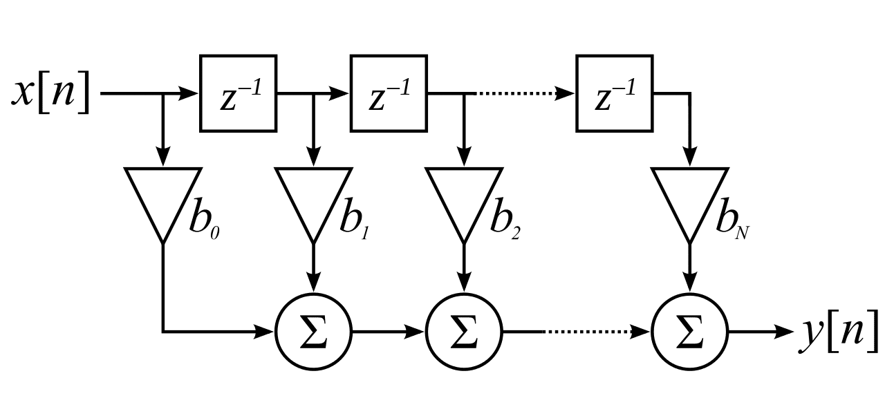
Figure 1: FIR filter design
Designing FIR Filter in Simulink Matlab
- Lets' now design a second order FIR filter using the system of the filter given in the equation below.
- Above is given a filter of 2nd order. We will now compare the above equation with a general equation given below, to find the co-efficient b0 , b1 ,b2 .
b0 = 2, b1 = 1,b2 =2 .
- Now, lets' design this filter in MATLAB's simulink. First of all open MATLAB and then simulink as we have been doing in previous tutorials and create a blank model to design a simple FIR filter. Open the library browser of simulink and from the commonly used blocks, select the constant block as shown in the figure below. This block will serve as the co-efficient of the equation.
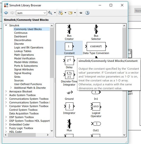
Figure 2: Constant block
- Next, we will be needing a delay block which will serve as the x[n-1] and x[n-2] delayed samples. The order of the filter will decide the number of delay blocks to be used in the filter design. In our example the order of filter is 2 and hence the number of delay block. From the commonly used blocks section, select the delay block and place it on the model as shown in the figure below:

Figure 3: Delay block
- The number of stages of an FIR filter to be designed will also depend on the order of the filter. If the order of the filter is N then the number of stages to be used in the filter design will be N+1. In our case the order of the filter is 2 and hence the stages will be 3. At the end of the filter stages we will have to sum up the output of all the stages as is obvious from the equation of our system. For this summation process, we have to use a sum block. From the Math operation section in simulink library browser, select the sum block and add it to the model as shown in the figure below:
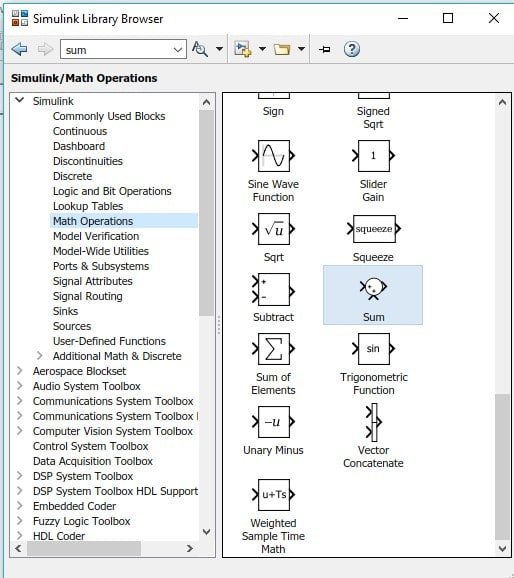
Figure 4: Sum block
- Also in order to multiply the co-efficient of each stage with the delayed input, we have to use some product block. In the library browser from the section of Math operations select the Product block and place it in the model as shown in the figure below:
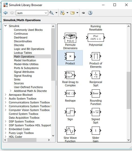
Figure 5: Product block
- Next step is to add some input source in order to see the response of the system correctly. The input source we will use here is Repeating Sequence Stairs. The purpose of using this block is to generate an impulse as we will see shortly how to do so. From the sources section of the library browser of simulink, select Repeating Sequence Stairs block and add it to model as shown in the figure below:
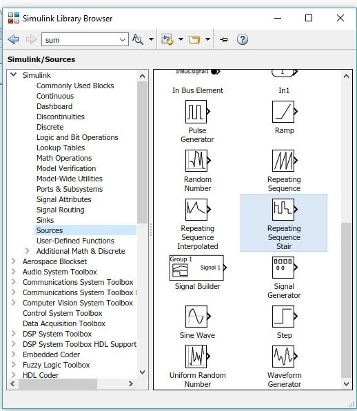
Figure 6: Input source
- In order to display the output of the filter, we also need some kind of oscilloscope to display input along side of output. From the sinks section of library browser select scope and add it to model as shown in the figure below:
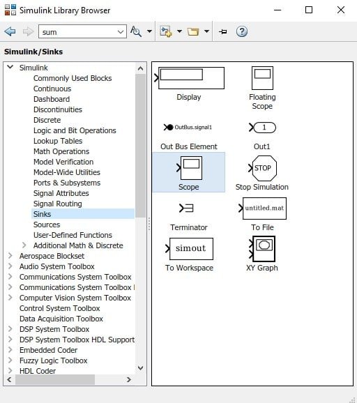
Figure 7: Scope
- Now lets move to the model we have created in the start to jump towards the designing part of the filter. As we have discussed previously, our filter will have three stages. We will design each stage step by step. First of all place the input source at the left and double click on it to change its input to an impulse. In the parameter block add the sequence of input as shown below:

Figure 8: Input sequence
- Now using the equation given for the filter, we will start designing from left to right. The first addend of the equation will make the first stage as shown in the figure below;
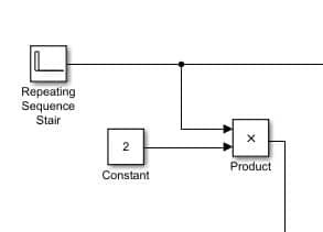
Figure 9: First stage
- The same input will be then used with a single delay to make the second stage and multiplied with the constant value of one as shown in the figure below:
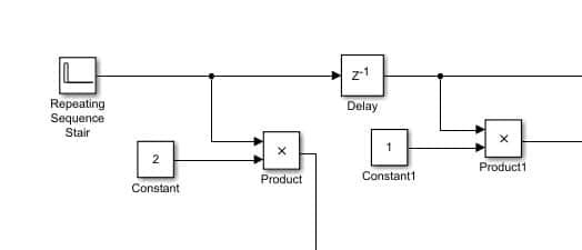
Figure 10: Second stage
- Same will happen in the case of third stage with one more delay block at the output of the first delay block to provide the 2 times delayed input i.e. x[n-2] as shown in the figure below:
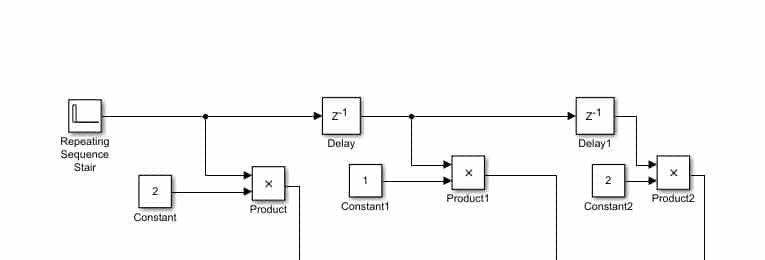
Figure 11: Third stage
- Now the output off all three stages will be added using sum block. But first change the number of inputs of the sum block as we have done previously. And at the output of the sum block connect a 2 input scope (one for the input and one for the output) as shown in the figure below;
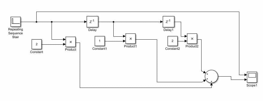
Figure 12: Complete block diagram
Now change the simulation stop time to 1 as we have done before and run the simulink model. After the completion of running double click on the scope and the output of the filter will look like the one shown in the figure below;
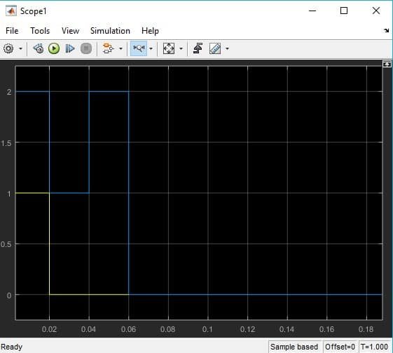
Figure 13: Output
The output of the filter is in accordance with the explanation in the introduction part.
Exercise:
- Design a third order FIR filter of the system given in the equation below.
(Hint: Number of delay blocks to be used will be 3)
Design Fir Filter Using Fourier Series Expansion Method Using Matlab
Source: https://microcontrollerslab.com/fir-filter-design-in-simulink-matlab/
0 Response to "Design Fir Filter Using Fourier Series Expansion Method Using Matlab"
Post a Comment